Rube Goldberg machine
(sub assembly )
-
As with any project taken on by an engineer it is necessary to understand the stakes that your project holds.
For this design project it was necessary to understand what stakes would be placed on my design so I address them effectively and in a time conscious manor.
What’s the point?
To effectively design and implement numerous engineering concepts for the sake of making one awesome Rube Goldberg sub assembly.
Primary Stake Holders:
Fellow Engineering Students of ME 382
Instructor
OSU Mechanical Engineering department
Desired outcome:
The capability to 3D print a well designed and mass producible sub assembly for a Rube Goldberg machine. That will effectively receive an output from a fellow classmates sub assembly.
In doing so, I would show comprehension of design and manufacturing practices and standards.
-
Benchmarking
Rolling-ball marble run
Design: Gravity driven rolling ball, Uses kinetic energy, Could use launchers
Components: Tiles, Tracks, Support columns, Steel/Glass marbles, Possible launcher (dc motor)
Power reqs: Gravity (main), AAA batteries for possible dc motor
Consumables: Steel/Glass marbles, Batteries, Gen. Replacements
Spring snap mousetrap
Design: Single action spring Trigger, Mousetrap car
Components: Wooden base, Steel spring, Strike bar, Trigger launch, Rivets and pins, String for Mousetrap car
Power reqs: Mech. spring energy, Manual reset
Consumables: Springs, String
Battery-powered toy launcher
Design: Electric launcher (DC motor), Launch trigger/switch (motion sensor in some cases)
Components: DC motor, Gearbox, Drive wheels, Tracks, On/off switch or button, Battery harness
Power reqs: AA batteries (3-6V)
Consumables: Batteries, Rubber wheels, Gears for gear box
-
Per class project info:
Your project is, of course, to design a subassembly of a class-wide Rube Goldberg machine.
Your functional analysis is important to this project for a few reasons -- primarily, designing for specific functions, instead of for specific components, is going to make concept generation more innovative and make it much more likely that you converge on an original device concept. Secondarily, this part of the process is where you will gain the terminology you need to describe your design concept's potential output functions, which will be critical for communicating with the students whose devices neighbor yours in the class-wide machine.
Per my stakeholder analysis: .
Functional cycle life > 1000 operating cycles
Dimension tolerance ± 0.5mm
Allowable load >50 N
Impact/impulse 5J
Cost $
Noise level dB
Reasonable dimensions lwh
Weight lbs
Assembly Time sec
Vibration Hz
-
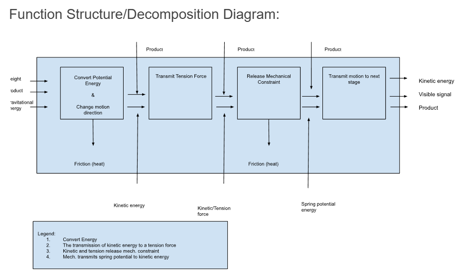
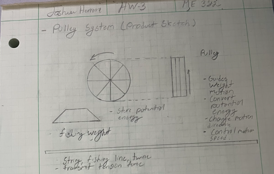
List of Functions (initially the idea was centered around a weighted pulley and spring launcher):
Store potential energy
Convert potential energy
Transmit tension force
Change motion direction
Release mechanical restraint
Trigger spring release
Guide weight motion
Control motion speed
Transmit motion
Indicate system activation
-
Here, along with the help of my peers I implemented:
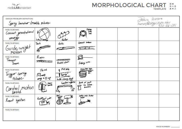
Set-Based Design, which encourages the consideration of multiple potential concept paths, instead of iterating a single idea. (Module 4 def)
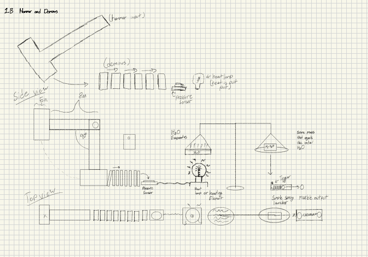
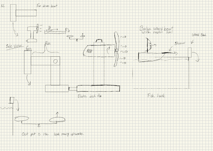
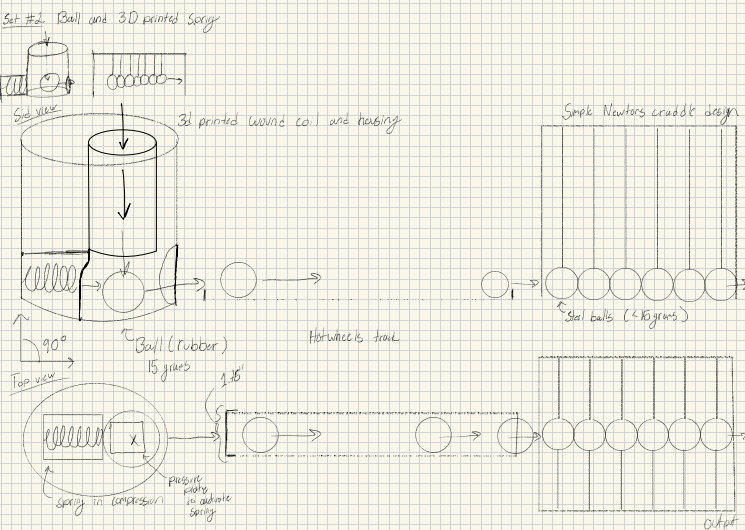
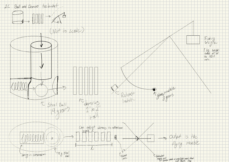
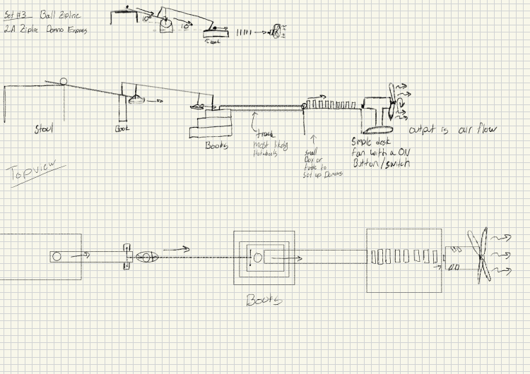
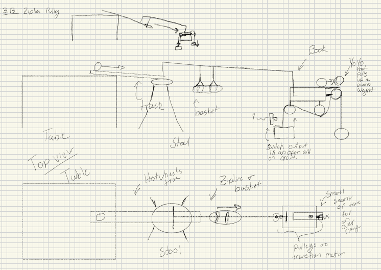
Pictured below with the title of Morphological Chart you can see 18 different tasks and subtasks. These where then combined into the proceeding 9 complete concept sketches implementing those subtasks and ideas from my peers.
-
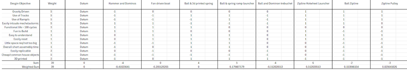
After the completion of those 9 design concepts I proceeded to create a Pugh chart. From which I made the following conclusion:
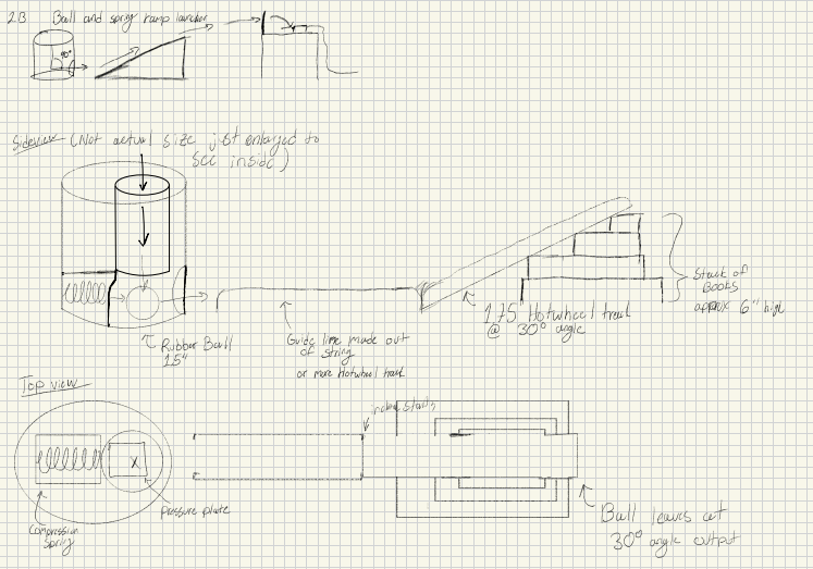
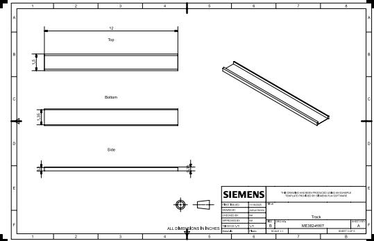
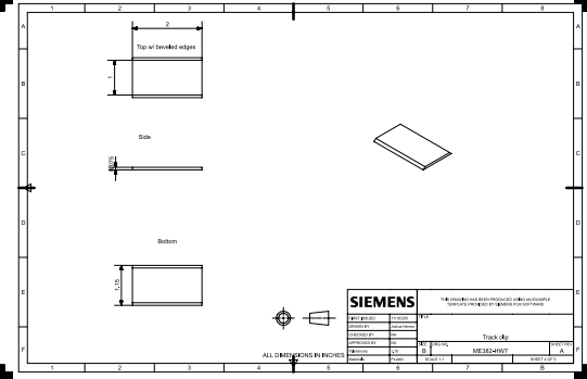
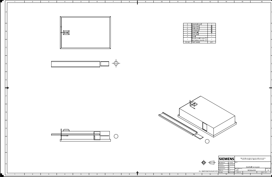
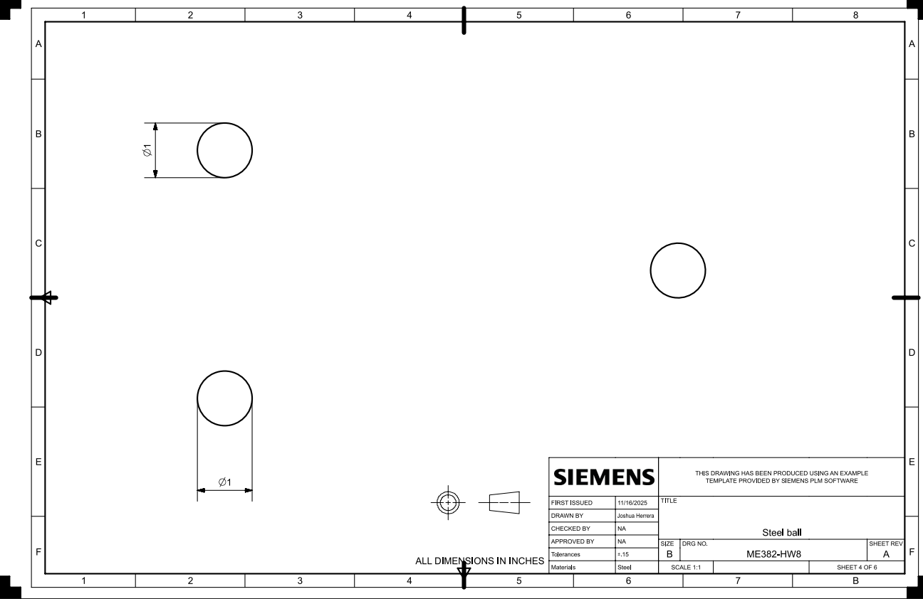
Based on the results of the Pugh chart evaluation, I selected the datum concept in which the primary output function is achieved through a marble or ball—of defined geometry and density—rolling down a ramp. This output mechanism aligns most effectively with the project’s design objectives, enabling reliable control over motion, timing, and energy transfer throughout the system.
Although the datum concept emerged as the most favorable, I intend to incorporate several functional elements and design parameters from the alternative concepts developed last week, where feasible, to enhance overall performance and design robustness.
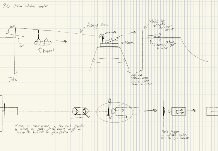
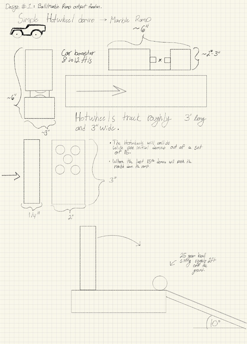
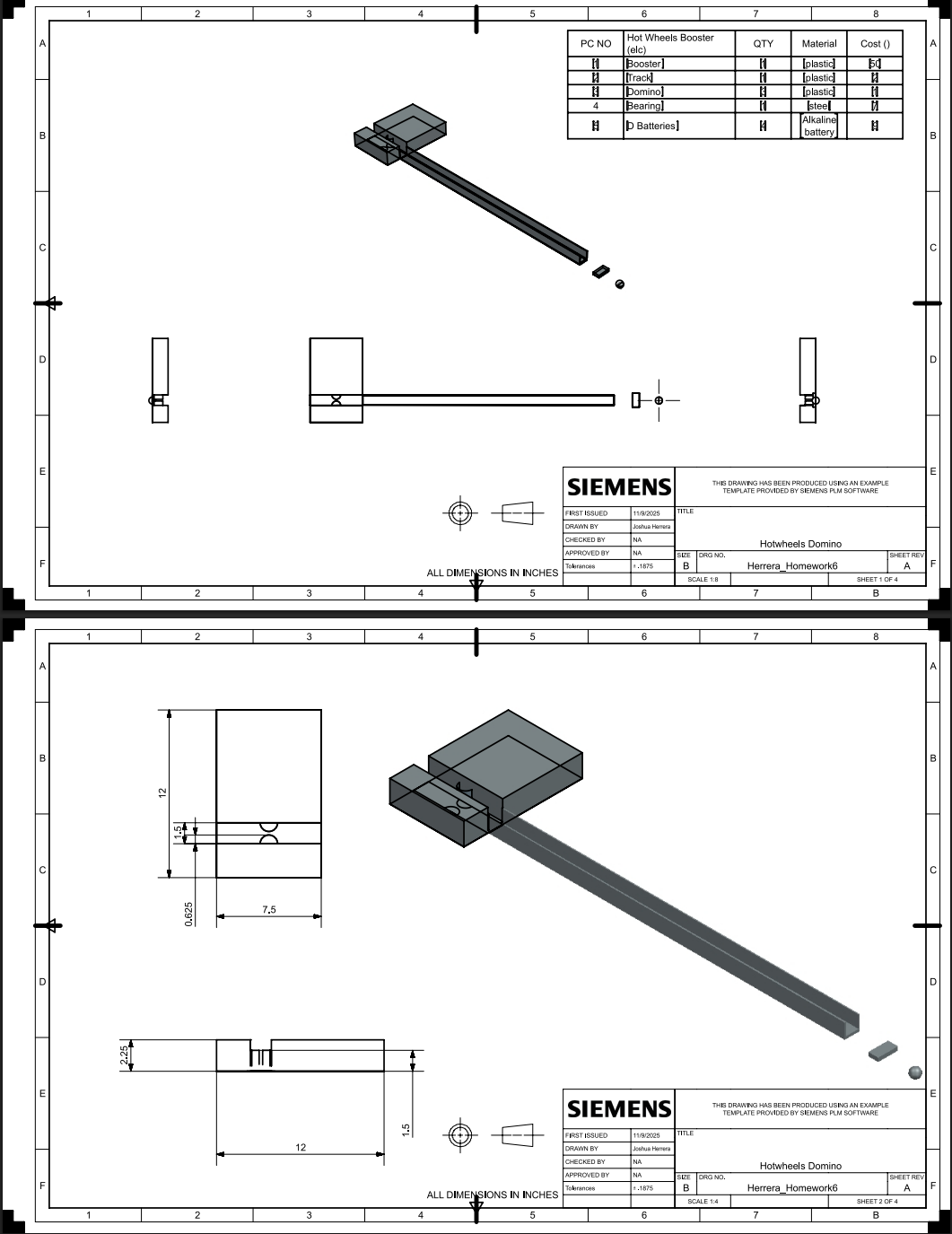
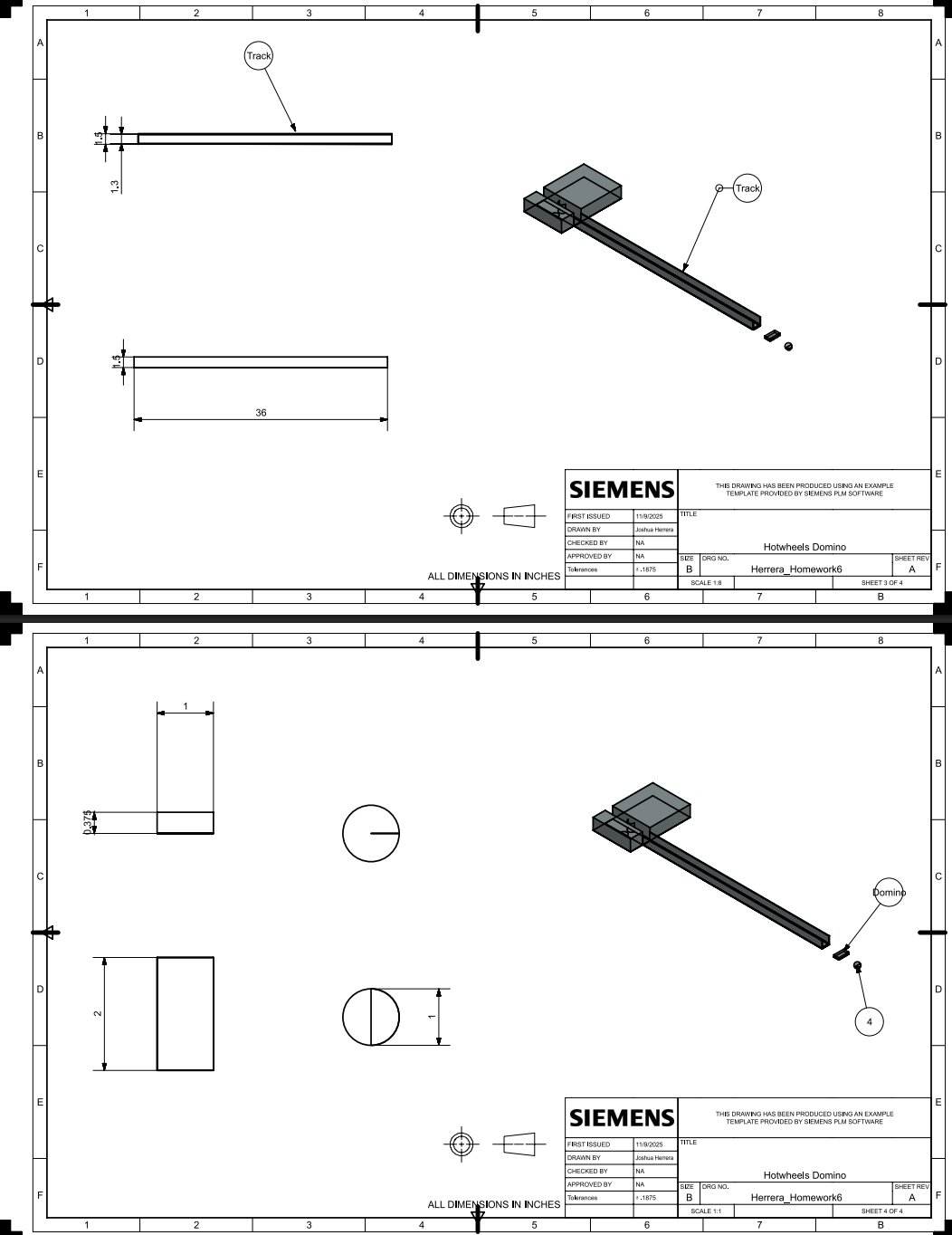
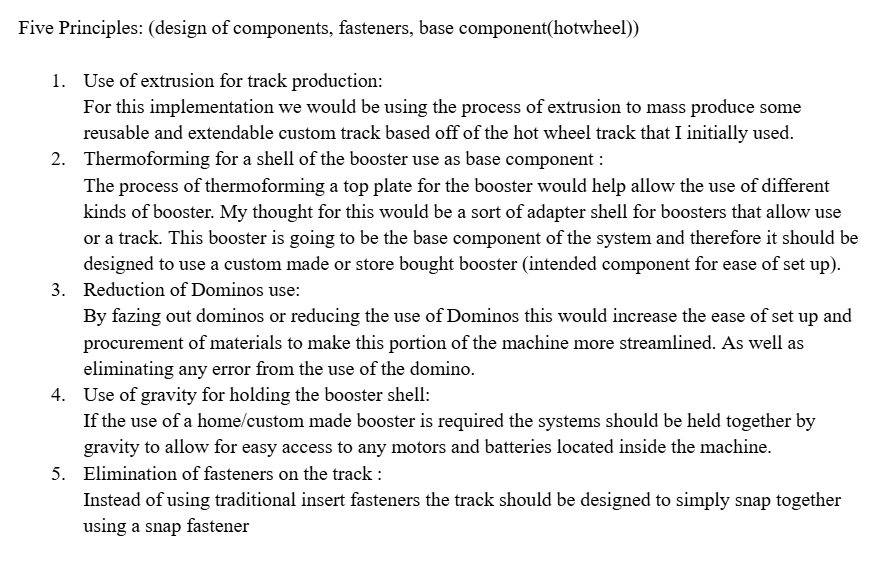
This would later be morphed into the Hot wheel-esque launcher.
The Pugh chart can be viewed below along with three more flushed out and polished concepts.
-
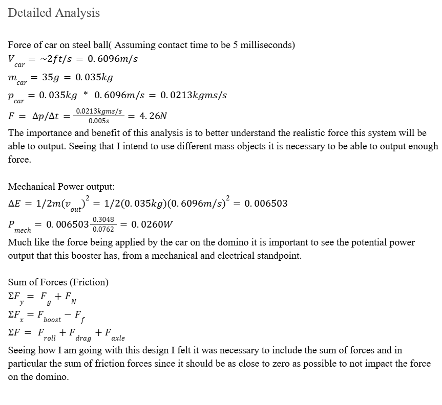
Force on the First domino: Assuming contact time to be 5 milliseconds
Vcar=~2ft/s=0.6096m/s
mcar=35g=0.035kg
pcar=0.035kg * 0.6096m/s=0.0213kgms/s
F= p/t=0.0213kgms/s0.005s=4.26N
Ball Potential Energy at top of the ramp:
PE =0.06 lbs* 2ft
Mechanical Power output:
E=1/2m(vout)2=1/2(0.035kg)(0.6096m/s)2=0.006503
Pmech=0.0065030.30480.0762=0.0260W
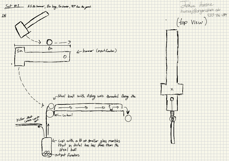
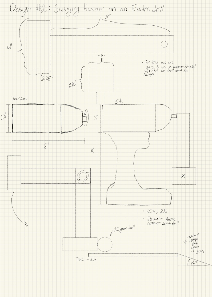
#2 Swinging Hammer and Electric drill
Powerlife:
P=172.78 rads/s (1.9672NM)=
t=40Wh~340=0.117 hrs=~7 minutes of runtime
Torque:
1650 Revs1min* 1 min60s*2pi rad1 rev=10367.5Rad60s=172.78 rad/s
T=340172.78=1.9672NM
Force of Hammer:
FHammer=1.9672NM/0.26035m=7.556N
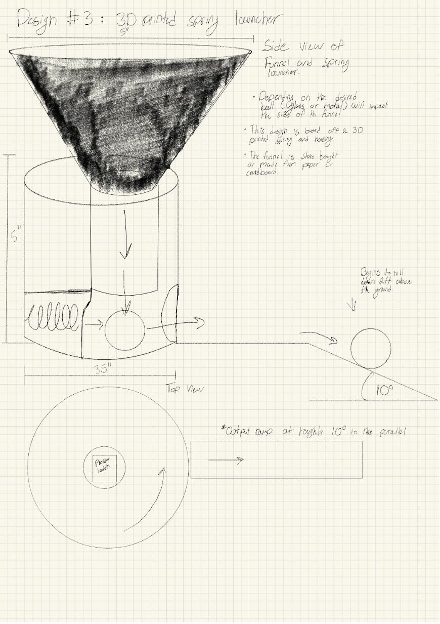
#3 3D printed Spring Launcher
What type of spring and what spring force is neededl:
Fsprig=mg=0.2(0.025kg)(9.8m/s)=0.049
Vertical force after funnel:
F=0.025kg*9.8m/s*0.127=0.03115N
Force on the retaining plate :
Fplate=Fspring=0.049N
-
To verify the feasibility of the electrical components I would us LTspice to simulate the circuit architecture prior construction. These simulations enable me to observe various circuitry behavior in varying conditions, while also allowing me to identify possible issues pertaining to voltage margins or current loading. This simulation would help reduce risk and the number of physical models needed during testing.
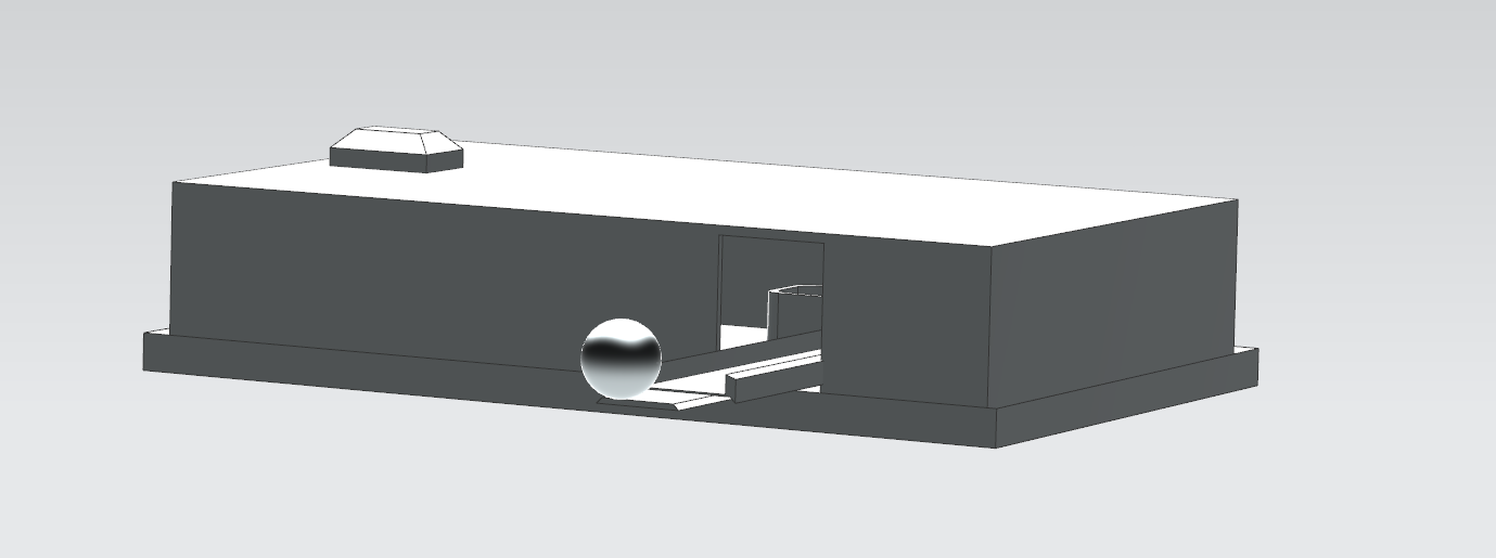
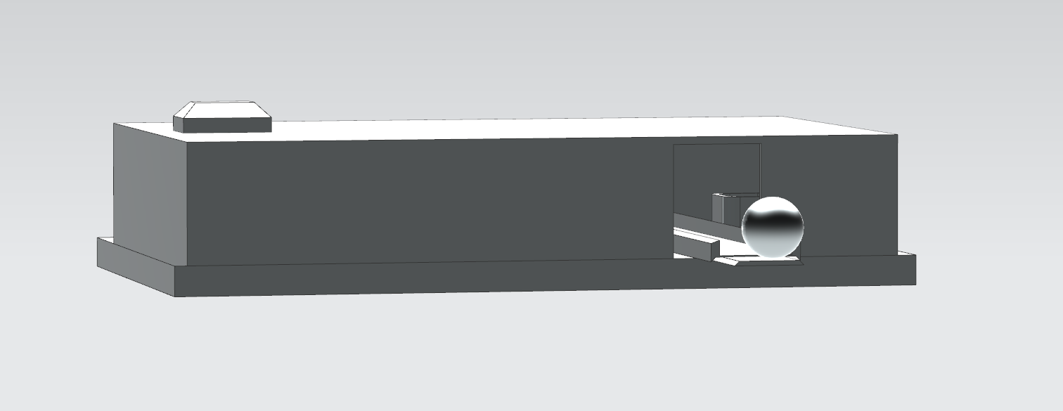
For mechanical performance, a more physics based modeling is needed. Particularly for modeling the interaction between the spinning motors and the car. I will be modeling the car as a sphere to help reduce the number of variables and overall complexity. This physics based modeling will allow me to better understand the acceleration enacted by the spinning rollers on the car, as well as frictional effects from the track and tack walls.
Thanks to the overall simplicity of this system, most of the forces can be calculated by hand and through standard dynamic relations.
The combination of electrical simulation, dynamic modeling and physical analysis ensures this system design is sound and well-justified.
-
Documentation of Peer review:
From Module 6: Design Review for Convergence
Hey Joshua,
I see we thought of a very similar idea for a spring powered marble launcher. I like the approach you took because it's much more compact. I used a much larger 3D printed spring that was housed outside of the main contraption. In your design how do you plan on triggering the spring once the ball is in the correct location?
From Module 10: Final Review
Thomas B.
Hey Joshua,
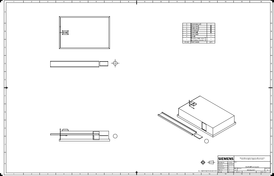
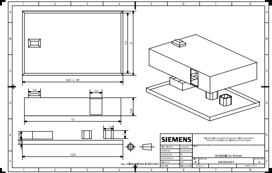
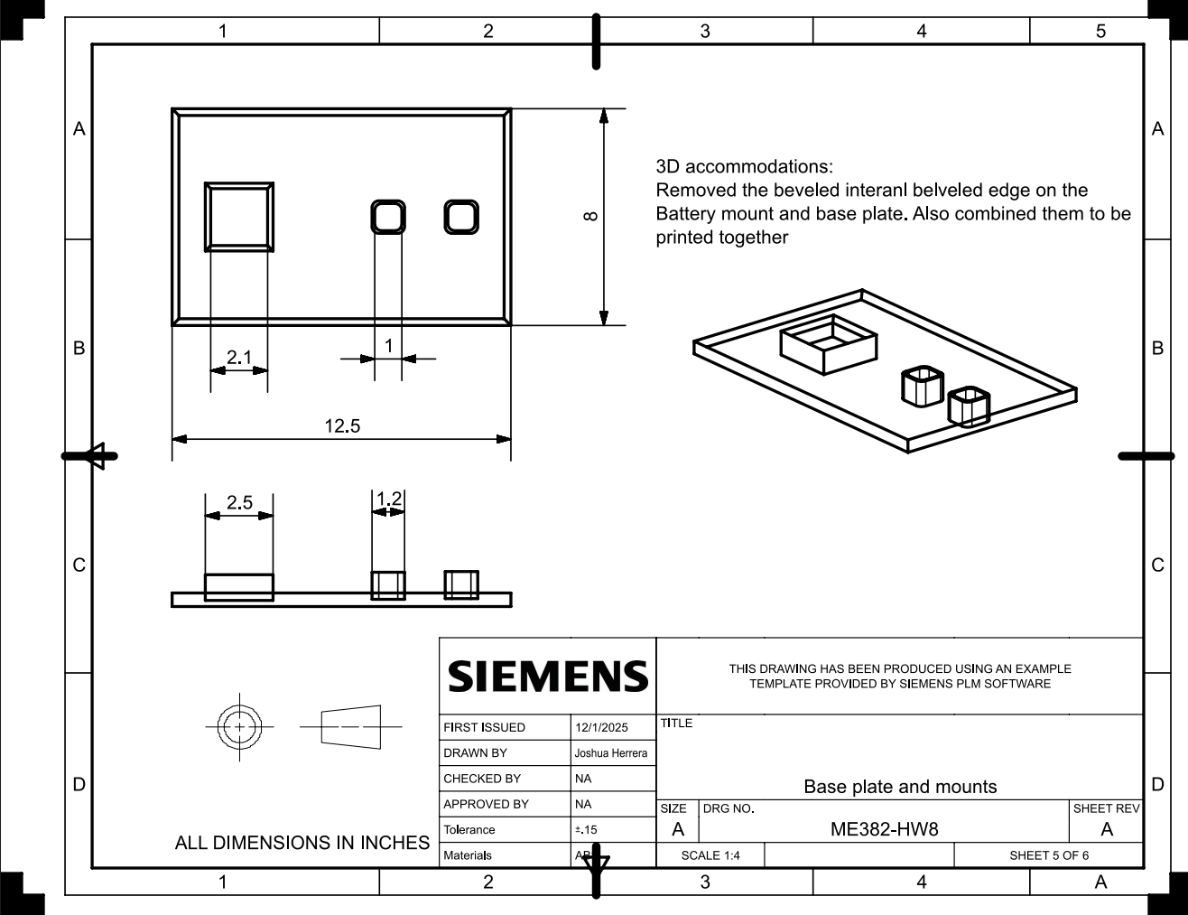
I like how you simplified the booster so the base, motor mounts, and battery pack are all printed together that seems like it will make motor alignment and assembly way more reliable. Your plan to use LTSPICE for the circuit side is solid, and pairing that with a physics model of motor-to-car contact should give you good insight into the actual boost.
Nicholas L.
Hi Joshua,
your design looks very clean and compact, which are both great attributes for these devices. Good idea modeling the car as a ball for now, as it will accomplish the same task with less work in CAD. Using LTspice is the perfect way to simulate your electronic components, but is there a way to simulate how the ball/Hot Wheels will react when rolling through your machine? You Could consider doing something like a force to get the ball rolling at a constant speed, and then a sudden very large force which you expect the motors to impart on the ball when it gets to that point, and see how it reacts coming out the other side.
Overall very good job, and I like your use of a Hot Wheels in your design.
-
Throughout this course and project, I have been challenged to design and implement a Rube Goldberg sub-assembly, and the process has been genuinely entertaining. It pushed me to refine both my concept-generation techniques and my ability to translate those concepts into functional designs.
By identifying the major stakeholders, outlining their design requirements, and examining similar existing systems, I was able to form a clear initial direction for what needed to be accomplished and how I intended to approach it. Through consistent peer interaction and iterative development, I gradually improved the effectiveness of my design and narrowed in on the most applicable sub-assembly for our class machine. Once I selected a design standard that aligned well with my requirements, I iterated the concept again and conducted preliminary physical analyses of the system and its components.
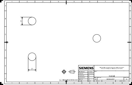
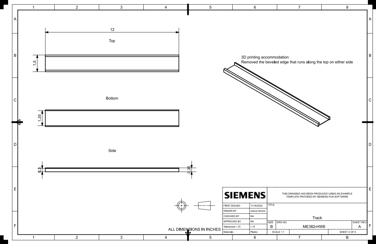
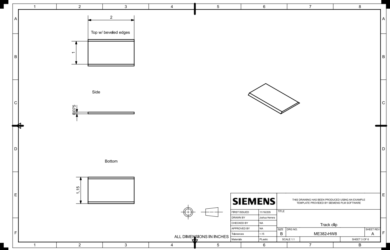
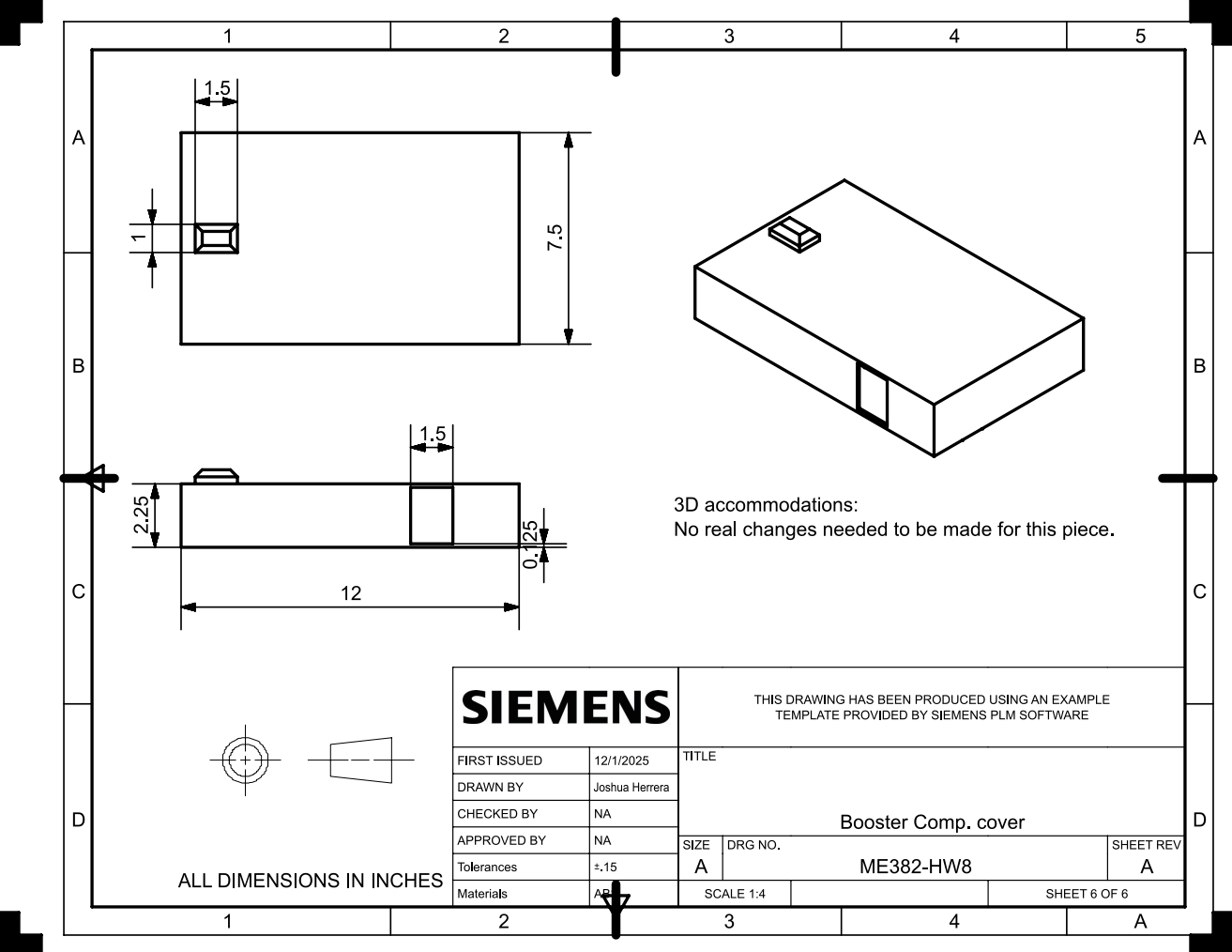
With this foundational analysis completed, I moved on to producing engineering drawings and renderings, which were then reviewed and critiqued by my peers. After incorporating additional feedback and adapting to new design constraints, I performed one final redesign of the sub-assembly. This last iteration focused on ensuring the component could be successfully manufactured through 3D printing—specifically optimized for ABS filament, which offered the best combination of performance and cost for my system.
-
Increase iteration numbers.
Increase number of peers to review your design, the more the merrier.
Be aware of tolerances and their impact to the components in your system.
Be aware of how system reequipments can change or update, make sure your design allows for the implementation of those changes.
DO NOT make up your mind right away, allow yourself to envision different possibilities and the interactions of subsystems.
DO NOT be afraid to start fresh, sometimes a system might seem like it will meet your Stake Holder and machine requirements but will do it inefficiently so it might be worth while to brainstorm and learn from the pitfalls of your design.